Fiber Optic Communication - The Future Of Networking & Data Transmission
Fiber optic communication is a method of transmitting information from one place to another by sending pulses of light through an optical fiber. The light forms an electromagnetic carrier wave that is modulated to carry information.
First developed in the 1970s, fiber-optic communication systems have revolutionized the telecommunications industry and have played a major role in the advent of the Information Age. Because of its advantages over electrical transmission, optical fibers have largely replaced copper wire communications in core networks. Optical fiber is used by many telecommunications companies to transmit telephone signals, Internet communication, and cable television signals. Researchers have reached internet speeds of over 100 petabits per second using fiber-optic communication.
Fiber's advantages has led to its use as the backbone of all of today's communications, telecom, Internet, CATV, etc. - even wireless, where towers are connected on fiber and antennas are using fiber up the towers.

This photo from the infancy of fiber optics (to the right) was used to illustrate that one tiny optical fiber could carry more communications signals than a giant copper cable. Today one single mode fiber could carry the same amount of communications as 1000 of those old copper cables!
Fiber offers thousands of times more bandwidth than copper cables and can go more than 1000 times further before needing repeaters - both of which contribute to the immense economic advantage of fiber optics over copper. You can do a similar analysis for using wireless transmission also, but wireless is limited by the available wireless spectrum which is overcrowded because of everyone's desire to use more mobile devices.
Why Convert From Copper Cable To Fiber Optic Cable?
If you need some convincing before you make your first fiber optic cable purchase keep the following facts in mind.
 Optical Fiber - Much More Efficient & Secure
Fiber optic cable operates much more efficiently and is more secure than traditional copper cabling. Fiber can transmit far more information over greater distance and with a higher clarity while offering a more secure connection. Fiber optic cable is resistant to electromagnetic interference and generates no radiation of its own. This point is important in locations where high levels of security must be maintained. Copper wire radiates energy that can be monitored. In contrast, taps in Fiber optic cable Fiber are easily detected. Copper cable, is also subject to problems with attenuation, capacitance, and crosstalk.
Optical Fiber - Does Not Require Grounding
Since fiber is made of glass, which is a bad electrical conductor, it does not require grounding and shields itself from other electrical interference. Fiber cables can be run near electrical cables without fear that it will weaken or interrupt the signal.
Optical Fiber - Corrosion Resistant
Fiber optic cable does not corrode and is not as sensitive to water or chemicals. This means you can safely run fiber cable in direct contact with dirt or in close proximity to chemicals (with the proper outer jacket materials).
Optical Fiber - The Safer Choice
Since fiber is not a good conductor of electricity, an installer or user will be safe from electrocution if there is a break in the outer jacket and the fiber is exposed.
The process of communicating using fiber-optics involves the following basic steps: Creating the optical signal involving the use of a transmitter, relaying the signal along the fiber, ensuring that the signal does not become too distorted or weak, receiving the optical signal, and converting it into an electrical signal.
Fiber (or fibre) consists of a strand of pure glass a little larger than a human hair. Fiber optic cable employs photons and pulsing laser light for the transmission of digital signals. Photons pass through the glass with negligible resistance. As light passes through the cable, its rays bounce off the cladding in different ways as shown below. The optic core of fiber optic cable is pure silicon dioxide. The electronic 1s and 0s of computers are converted to optically coded 1s and 0s. A light-emitting diode on one end of the cable then flashes those signals down the cable. At the other end, a simple photodetector collects the light and converts it back to electrical signals for transmission over copper cable networks.

Step index multimode was the first fiber design but is too slow for most uses, due to the dispersion caused by the different path lengths of the various modes. Step index fiber is rare - only POF uses a step index design today.
Graded index multimode fiber uses variations in the composition of the glass in the core to compensate for the different path lengths of the modes. It offers hundreds of times more bandwidth than step index fiber - up to about 2 gigahertz.
Singlemode fiber shrinks the core down so small that the light can only travel in one ray. This increases the bandwidth to almost infinity - but it's practically limited to about 100,000 gigahertz - that's still a lot!

Optical fiber consists of a core and a cladding layer, selected for total internal reflection due to the difference in the refractive index between the two. In practical fibers, the cladding is usually coated with a layer of acrylate polymer or polyimide. This coating protects the fiber from damage but does not contribute to its optical waveguide properties.
Individual coated fibers (or fibers formed into ribbons or bundles) then have a tough resin buffer layer and/or core tube(s) extruded around them to form the cable core. Several layers of protective sheathing, depending on the application, are added to form the cable.
Rigid fiber assemblies sometimes put light-absorbing ("dark") glass between the fibers, to prevent light that leaks out of one fiber from entering another. This reduces cross-talk between the fibers, or reduces flare in fiber bundle imaging applications.
A “dopant” is added to the core to actually make it less pure than the cladding. This changes the way the core transmits light. Because the cladding has different light properties than the core, it tends to keep the light within the core. Because of these properties, fiber optic cable can be bent around corners and can be extended over distances of up to 100 miles.
A typical laser transmitter can be pulsed billions of times per second. In addition, a single strand of glass can carry light in a number of wavelengths (colors), meaning that the data-carrying capacity of fiber optic cable is potentially thousands of times greater than copper cable.
- Plastic cable, which works only over a few meters, is inexpensive and works with inexpensive components.
- Plastic-coated silica cable offers better performance than plastic cable at a little more cost.
- Single-index monomode fiber cable is used to span extremely long distances. The core is small and provides high bandwidth at long distances. Lasers are used to generate the light signal for single-mode cable. This cable is the most expensive and hardest to handle, but it has the highest bandwidths and distance ratings.
- Step-Index multimode cable has a relatively large diameter core with high dispersion characteristics. The cable is designed for the LAN environment and light is typically generated with a LED (light-emitting diode).
- Graded-index multimode cable has multiple layers of glass that contain dispersions enough to provide increases in cable distances.
Cable specifications list the core and cladding diameters as fractional numbers. For example, the minimum recommended cable type for FDDI (Fiber Distributed Data Interface) is 62.5/125 micron multimode fiber optic cable.That means the core is 62.5 microns and the core with surrounding cladding is a total of 125 microns.
- The core specifications for step-index and graded-index multimode cables range from 50 to 1,000 microns.
- The cladding diameter for step mode cables ranges from 125 to 1,050 microns.
- The core diameter for single-mode step cable is 4 to 10 microns, and the cladding diameter is from 75 to 125 microns.

For indoor applications, the jacketed fiber is generally enclosed, with a bundle of flexible fibrous polymer strength members like aramid (e.g. Twaron or Kevlar), in a lightweight plastic cover to form a simple cable. Each end of the cable may be terminated with a specialized optical fiber connector to allow it to be easily connected and disconnected from transmitting and receiving equipment.
For outdoor applications or use in more strenuous environments, a much more robust cable construction is required. In loose-tube construction the fiber is laid helically into semi-rigid tubes, allowing the cable to stretch without stretching the fiber itself. This protects the fiber from tension during laying and due to temperature changes. Loose-tube fiber may be "dry block" or gel-filled. Dry block offers less protection to the fibers than gel-filled, but costs considerably less. Instead of a loose tube, the fiber may be embedded in a heavy polymer jacket, commonly called "tight buffer" construction. Tight buffer cables are offered for a variety of applications, but the two most common are "Breakout" and "Distribution".
Breakout Cables normally contain a ripcord, two non-conductive dielectric strengthening members (normally a glass rod epoxy), an aramid yarn, and 3 mm buffer tubing with an additional layer of Kevlar surrounding each fiber. The ripcord is a parallel cord of strong yarn that is situated under the jacket(s) of the cable for jacket removal. Distribution Cables have an overall Kevlar wrapping, a ripcord, and a 900 micrometer buffer coating surrounding each fiber. These fiber units are commonly bundled with additional steel strength members, again with a helical twist to allow for stretching.
A critical concern in outdoor cabling is to protect the fiber from contamination by water. This is accomplished by use of solid barriers such as copper tubes, and water-repellent jelly or water-absorbing powder surrounding the fiber.
Finally, the cable may be armored to protect it from environmental hazards, such as construction work or gnawing animals. Undersea cables are more heavily armored in their near-shore portions to protect them from boat anchors, fishing gear, and even sharks, which may be attracted to the electrical power that is carried to power amplifiers or repeaters in the cable.
Modern cables come in a wide variety of sheathings and armor, designed for applications such as direct burial in trenches, dual use as power lines, installation in conduit, lashing to aerial telephone poles, submarine installation, and insertion in paved streets.
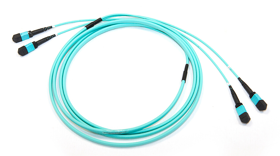
To purchase your fiber cables, please click link below:
Fiber Patch Cables
Read more »


 Remember, return loss is different than insertion loss, which refers to the amount of optical power lost through a connector or cable length. Insertion loss is what we use to determine loss budgets. Achieving low insertion loss is typically easier with UPC connectors due to less air gaps than APC connectors. However, manufacturing techniques have improved significantly to create more precise angles on APC connectors and bring insertion loss down closer to that of UPC connectors.