telecomvideos.com
Welcome
Login / Register

Latest Articles


  • COMPUFOX SFP+ Direct Attach Copper Cables Solution

    Overview
    SFP+ Direct Attach Copper Cable, also known as Twinax Cable, is an SFP+ cable assembly used in rack connections between servers and switches. It consists of a high speed copper cable and two SFP+ copper modules. The SFP+ copper modules allow hardware manufactures to achieve high port density, configurability and utilization at a very low cost and reduced power budget.

    Direct Attach Cable assemblies are a high speed, cost-effective alternative to fiber optic cables in 10Gb Ethernet, 8Gb Fibre Channel and InfiniBand applications. They are suitable for short distances, making them ideal for highly cost-effective networking connectivity within a rack and between adjacent racks. They enable hardware OEMs and data center operators to achieve high port density and configurability at a low cost and reduced power requirement.

    Compufox SFP+ copper cable assemblies meet the industry MSA for signal integrity performance. The cables are hot-removable and hot-insertable: You can remove and replace them without powering off the switch or disrupting switch functions. A cable comprises a low-voltage cable assembly that connects directly into two SFP+ ports, one at each end of the cable. The cables use high-performance integrated duplex serial data links for bidirectional communication and are designed for data rates of up to 10 Gbps.

    Types of SFP+ Direct Attach Copper Cables

    SFP+ Direct Attach Copper Cable assemblies generally have two types which are Passive and Active versions.

    SFP+ Passive Copper Cable
    SFP+ passive copper cable assemblies offer high-speed connectivity between active equipment with SFP+ ports. The passive assemblies are compatible with hubs, switches, routers, servers, and network interface cards (NICs) from leading electronics manufacturers like Cisco, Juniper, etc.
     
    SFP+ Active Copper Cable
    SFP+ active copper cable assemblies contain low power circuitry in the connector to boost the signal and are driven from the port without additional power requirements. The active version provides a low cost alternative to optical transceivers, and are generally used for end of row or middle of row data center architectures for interconnect distances of up to 15 meters.


    Applications of SFP+ Direct Attach Copper Cables

    -Networking – servers, routers and hubs
    -Enterprise storage
    -Telecommunication equipment
    -Network Interface Cards (NICs)
    -10Gb Ethernet and Gigabit Ethernet (IEEE802.3ae)
    -Fibre Channel over Ethernet: 1, 2, 4 and 8G
    -InfiniBand standard SDR (2.5Gbps), DDR (5Gbps), and QDR (10Gbps)
    -Serial data transmission
    -High capacity I/O in Storage Area Networks, Network Attached Storage, and Storage Servers
    -Switched fabric I/O such as ultra high bandwidth switches and routers
    -Data center cabling infrastructure
    -High density connections between networking equipment


    Compufox SFP+ Direct Attach Copper Cables Solution

    Compufox SFP+ twinax copper cables are avaliable with custom version and brand compatible version. All of them are 100% compatible with major brands like Cisco, HP, Juniper, Enterasys, Extreme, H3C and so on. If you want to order high quality compatible SFP+ cables and get worldwide delivery, we are your best choice.

    For instance, our compatible Cisco SFP+ Copper Twinax direct-attach cables are suitable for very short distances and offer a cost-effective way to connect within racks and across adjacent racks. We can provide both passive Twinax cables in lengths of 1, 3 and 5 meters, and active Twinax cables in lengths of 7 and 10 meters. (Tips: The lengths can be customized up to the customers' requirements.)

    Features
    -1m/3m/5m/7m/10m/12m available
    -RoHS Compatible
    -Enhanced EMI suppression
    -Low power consumption
    -Compatible to SFP+ MSA
    -Hot-pluggable SFP 20PIN footprint
    -Parallel pair cable
    -24AWG through 30AWG cable available
    -Data rates backward compatible to 1Gbps
    -Support serial multi-gigabit data rates up to 10Gbps
    -Support for 1x, 2x, 4x and 8x Fibre Channel data rates
    -Low cost alternative to fiber optic cable assemblies
    -Pull-to-release retractable pin latch
    -I/O Connector designed for high speed differential signal applications
    -Temperature Range: 0-70°C
    -Passive and Active assemblies available (Active Version: Low Power Consumption: < 0.5W Power Supply: +3.3V)


    FAQ of Compufox SFP+ Direct Attach Copper Cables

    Q: What are the performance requirements for the cable assembly?
    A: Our SFP+ copper passive and active cable assemblies meet the signal integrity requirements defined by the industry MSA SFF-8431. We can custom engineer cable assemblies to meet the requirements of a customer’s specific system architecture.

    Q: Are passive or active cable assemblies required?
    A: Passive cables have no signal amplification in the assembly and rely on host system Electronic Dispersion Compensation (EDC) for signal amplification/equalization. Active cable assemblies have signal amplification and equalization built into the assembly. Active cable assemblies are typically used in host systems that do not employ EDC. This solution can be a cost savings to the customer.

    Q: What wire gauge is required?
    A: We offer SFP+ cable assemblies in wire gauges to support customers' specific cable routing requirements. Smaller wire gauges results in reduced weight, improved airflow and a more flexible cable for ease of routing.

    Q: What cable lengths are required?
    A: Cable length and wire gauge are related to the performance characteristics of the cable assembly. Longer cable lengths require heavier wire gauge, while shorter cable lengths can utilize a smaller gauge cable.

    For all you SFP+ Direct attach cables, please see link below. We carry compatible cables for most major brands.

    http://www.compufox.com/SFP_Cables_s/337.htm


    Read more »
  • Identify Types of Network Cables and Connectors

    There are three types of network cables: fiber, twisted pair, and coaxial.

    Fiber is the most expensive of the three and can run the longest distance. A number of types of connectors can work with fiber, but three you must know are SC, ST, and LC.

    Twisted pair is commonly used in office settings to connect workstations to hubs or switches. It comes in two varicties: unshielded (UTP) and shielded (STP), The two types of connectors commonly used are RJ-11 (four wires and popular with telephones), and RJ-45 (eight wires and used with xBaseT networks—100BaseT, 1000BaseT, and so forth). Two common wiring standards are T568A and T568B.

    Coaxial cabling is not as popular as it once was, but it's still used with cable television and some legacy networks. The two most regularly used connectors are F-conectors (television cabling) and BNC (10Base2, and so on).

    Fiber

    Fiber-optic cabling is the most expensive type. Although it's an excellent medium, it's often not used because of the cost of implementing it. It has a glass core within a rubber outer coating and uses beams of light rather than electrical signals to relay data. Because light doesn't diminish over distance the way electrical signals do, this cabling can run for distances measured in kilometers with transmission speeds from 100 Mbps up to 1 Gbps higher.

    Fiber optic cable

    Often, fiber is used to connect runs to wiring closets where they break out into UTP or other cabling types, or as other types of backbones. Fiber-optic cable can use either ST, SC, or LC connector. ST is a barrel-shaped connector, whereas SC is squared and easier to connect in small spaces.The LC connector looks similar to SC but adds a flange on the top (much like an RJ-45 connector) to keep it securely connected.

    st sc lc connectors

    Note: In addition to these listed in the A + objectives, other connectors are used with fiber. FC connectors may also be used but are not as common. MT-RJ is a popular connector for two fibers in a small form factor.

    Twisted Pair

    There are two primary types of twisted-pair cabling (with categories beneath cach that are shielded twisted pair (STP) and unshielded twisted pair (UTP). In both cases, the cabling is made up of pairs of wires twisted around each other.

    UTP offers no shielding (hence the name) and is the network cabling type most prone to outside interference. The interference can be from a fluorescent light ballast, eletrical motor, or other such source (known as eletromagnetic interference [EMI]) or from wires being too close together and signals jumping across them (known as crosstalk), STP adds a foil shield around the twisted wires to protect against EMI.

    Twisted Pair

    STP cable uses IBM data connector (IDC) or universal data connector (UDC) ends and connects to token ring networks. While you need to know STP for the exam, you are not required to have any knowledge of the connectors associated with it. You must, however, know that most UTP cable uses RJ-45 connectors, which look like telephone connectors (RJ-11) but have eight wires instead of four.

    RJ-45 connectors

    Two wiring standards are commonly used with twisted-pair cabling:T568A and T568B (sometimes referred to simply as 568A and 568B). These are telecommunications standards from TIA and EIA that specify the pin arrangements for the RJ-45 connectors on UTP or STP cables. The number 568 refers to the order in which the wires within the Category 5 cable are terminated and attached to the connector. The signal is identical for both.

    T568A was the first standard, released in 1991. Ten years later, in 2001, T568B was released. Pin numbers are read left to right, with the connector tab facing down. Notice that the pin-outs stay the same, and the only difference is in the color coding of the wiring.


    Pin assignments for T568A and T568B

    Note: Mixing cables can cause communication problems on the network. Before installing a network or adding a new component to it, make sure the cable being used is in the correct wiring standard.

    Coaxial

    Coaxial cable, or coax, is one of the oldest media used in networks. Coax is built around a center conductor or core that is used to carry data from point to point. The center conductor has an insulator wrapped around it, a shield over the insulator, and a nonconductive sheath around the shielding. This construction allows the conducting core to be relatively free from outside interference. The shielding also prevents the conducting core from emanating signals externally from the cable.

    Note: Before you read any further, accept the fact that the odds are incredibly slim that you will ever need to know about coax for a new installation in the real world (with the possible exception of RG-6, which is used from the wall to cable modem). If you do come across it, it will be in an existing installation and one of the first things you'll recommend is that it be changed. 

    Read more »
  • Basics of Fiber Optic Splicing

    Fiber Optics Splicing is becoming  more and more a common skill requirement for cabling technicians. A fiber optic splice is defined by the fact that it gives a permanent or relatively permanent connection between two fiber optic cables. Fiber optic cables might have to be spliced together for a number of reasons—for example, to create a link of a particular length, or to repair a broken cable or connection. As fiber optic cables are generally only manufactured in lengths up to about 5 km, when lengths of 10 km are required, for example, then it is necessary to splice two lengths together to make a permanent connection.

    Classification of Techniques Used for Optical Fiber Splicing

    Mechanical splices
    The mechanical splices are normally used when splices need to be made quickly and easily. Mechanical fiber optic splices can take as little as five minutes to make, although the level of light loss is around ten percent. However this level of better than that which can be obtained using a connector. Some of the sleeves for mechanical fibre optic splices are advertised as allowing connection and disconnection. In this way a mechanical splice may be used in applications where the splice may be less permanent.


    Fusion splices
    This type of connection is made by fusing or melting the two ends together. This type of splice uses an electric arc to weld two fiber optic cables together and it requires specialised equipment to perform the splice. Fusion splices offer a lower level of loss and a high degree of permanence. However they require the use of the expensive fusion splicing equipment.

    Mechanisms of Light Loss at Optical Fiber Joint

    When joining optical fibers, the opposed cores must be properly aligned. Optical fiber splice loss occurs mostly in the following manner.

    Poor concentricity
    Poor concentricity of joined optical fibers causes a splice loss. In the case of general purpose single-mode fibers, the value of splice loss is calculated roughly as the square of the amount of misalignment multiplied by 0.2. (For example, if the light source wavelength is 1310 nm, misalignment by 1 µm results in approximately 0.2 dB of loss.)

    Poor concentricity
    Axial run-out
    A splice loss occurs due to an axial run-out between the light axes of optical fibers to be joined. For example, it is necessary to avoid an increased angle at fiber cut end when using an optical fiber cleaver before fusion splicing, since such an angle can result in splicing of optical fibers with run-out.

    Axial run-out
    Gap
    An end gap between optical fibers causes a splice loss. For example, if optical fiber end faces are not correctly butt-joined in mechanical splicing, a splice loss.
     
    An end gap between optical fibers
    Reflection
    An end gap between optical fibers results in 0.6 dB of return loss at the maximum due to the change in refractive index from the optical fiber to the air. In addition, the whole optical fiber ends should be cleaned because loss can also occur due to dirt between optical fiber ends.

    Classification and Principles of Fusion Splices

    Fusion splicing is classified into the two methods, as follows:

    Core alignment

    Optical fiber cores observed with a microscope are positioned with the help of image processing so that they are concentrically aligned. Then, an electric arc is applied to the fiber cores. The fusion splicer used has cameras for observation and positioning in two directions.

    Fs core_alignment.jpg

    Stationary V-groove alignment

    This fusion splicing method uses V-grooves produced with high precision to position and orient optical fibers and utilizes the surface tension of melted optical fibers for alignment effects (cladding alignment). Splices made by this method achieve low loss thanks to the recent advancement of optical fiber production technology, which has improved the dimensional accuracy regarding the placement of core. This method is primarily used for splicing a multi-fiber cable in a single action.

    Fs V-groove.jpg
     

    Tips for Better Splices:

    1. Thoroughly and frequently clean your splicing tools. When working with fiber, keep in mind that particles not visible to the naked eye could cause tremendous problems when working with fiber optics. "Excessive" cleaning of your fiber and tools will save you time and money down the road.
     
    2. Properly maintain and operate your cleaver. The cleaver is your most valuable tool in fiber splicing. Within mechanical splicing you need the proper angle to insure proper end faces or too much light escaping into the air gaps between the two fibers will occur. The index matching gel will eliminate most of the light escape but cannot overcome a low quality cleave. You should expect to spend around $200 to $1,000 for a good quality cleaver suitable for mechanical splicing.
     
    For Fusion splicing, you need an even more precise cleaver to achieve the exceptional low loss (0.05 dB and less). If you have a poor cleave the fiber ends might not melt together properly causing light loss and high reflection problems. Expect to pay $1,000 to $4,000 for a good cleaver to handle the precision required for fusion splicing. Maintaining your cleaver by following manufacturer instructions for cleaning as well as using the tool properly will provide you with a long lasting piece of equipment and ensuring the job is done right the first time.
     
    3. Fusion parameters must be adjusted minimally and methodically (fusion splicing only). If you start changing the fusion parameters on the splicer as soon as there is a hint of a problem you might lose your desired setting. Dirty equipment should be your first check and them continue with the parameters. Fusion time and fusion current are the two key factors for splicing. Different variables of these two factors can produce the same splice results. High time and low current result in the same outcome as high current and low time. Make sure to change one variable at a time and keep checking until you have found the right fusion parameters for your fiber type.
    Read more »
  • OTDR (Optical Time Domain Reflectometer) Dead Zone Tutorial


    OTDR (Optical Time Domain Reflectometer) is a familiar fiber test instrument for technicians or installers to characterize an optical fiber. To understand the specifications which may affect the performance of OTDR can help users get maximum performance from their OTDRs. This tutorial will introduce one of the key specifications—Dead Zone.

    What Is a Dead Zone?

    The OTDR dead zone refers to the distance (or time) where the OTDR cannot detect or precisely localize any event or artifact on the fiber link. It is always prominent at the very beginning of a trace or at any other high reflectance event.

    OTDR_Trace
    Why makes a Dead Zone occur?

    OTDR dead zone is caused by a Fresnel reflection (mainly caused by air gap at OTDR connection) and the subsequent recovery time of the OTDR detector. When a strong reflection occurs, the power received by the photodiode can be more than 4,000 times higher than the backscattered power, which causes detector inside of OTDR to become saturated with reflected light. Thus, it needs time to recover from its saturated condition. During the recovering time, it can not detect the backscattered signal accurately which results in corresponding dead zone on OTDR trace. This is like when your eyes need to recover from looking at the bright sun or the flash of a camera. In general, the higher the reflectance, the longer the dead zone is. Additionally, dead zone is also influenced by the pulse width. A longer pulse width can increase the dynamic range which results in a longer dead zone.

    OTDR connection
    Event Dead Zones & Attenuation Dead Zone

    In general, dead zones on an OTDR trace can be divided into event dead zone and attenuation dead zone.

    OTDR_dead_zone
    Event Dead Zone

    The event dead zone is the minimum distance between the beginning of one reflective event and the point where a consecutive reflective event can be detected. According to the Telcordia definition, event dead zone is the location where the falling edge of the first reflection is 1.5 dB down from the top of the first reflection.

    EDZ
    Attenuation Dead Zone

    The attenuation dead zone is the minimum distance after which a consecutive non-reflective event can be detected and measured. According to the Telcordia definition, it is the location where the signal is within 0.5 dB above or below the backscatter line that follows the first pulse. Thus, the attenuation dead zone specification is always larger than the event dead zone specification.

    ADZ

    Note: In general, to avoid problems caused by the dead zone, a launch cable of sufficient length is always used when testing cables which allows the OTDR trace to settle down after the test pulse is sent into the fiber so that users can analyze the beginning of the cable they are testing.

    The Importance of Dead Zones

    OTDR_test
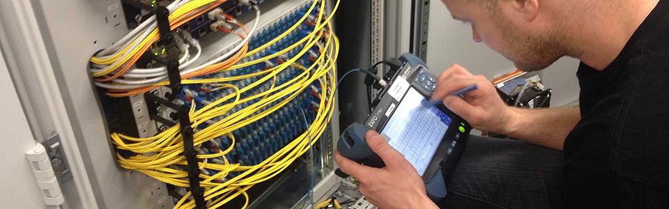
There is always at least one dead zone in every fiber—where it is connected to the OTDR. The existence of dead zones is an important drawback for OTDR, specially in short-haul applications with a large number of fiber optic components. Thus, it is important to minimize the effects of dead zones wherever possible.

    As mentioned above, dead zones can be reduced by using a lower pulse width, but it will decrease the dynamic range. Thus, it is important to select the right pulse width for the link under test when characterizing a network or a fiber. In general, short pulse width, short dead zone and low power are used for premises fiber testing and troubleshooting to test short links where events are closely spaced, while a long pulse width, long dead zone and high power are used for long-haul fiber testing and communication to reach further distances for longer networks or high-loss networks.

    The shortest-possible event dead zone allows the OTDR to detect closely spaced events in the link. For instance, testing fibers in premises networks (particularly in data centers) requires an OTDR with short event dead zones since the patch cords of the fiber link are often very short. If the dead zones are too long, some connectors may be missed and will not be identified by the technicians, which makes it harder to locate a potential problem.

    Short attenuation dead zones enable the OTDR not only to detect a consecutive event but also to return the loss of closely spaced events. For instance, the loss of a short patch cord within a network can now be known, which helps technicians to have a clear picture of what is actually inside the link.

    Summary

    OTDR is one of the most versatile and widely used fiber optic test equipment which offers users a quick, accurate way to measure insertion loss and shows the overview of the whole system you test. Dead zone, with two general types, is an important specification of OTDR. It is necessary for users to understand dead zone and select the right configuration in order to get maximum OTDR performance during test. In addition, OTDRs of different brands are designed with different minimum dead zone parameters since manufacturers use different testing conditions to measure the dead zones. Users should choose the suitable one according to the requirements and pay particular attention to the pulse width and the reflection value.


    Read more »
  • Fiber Media Converter Tutorial

    Fiber media converter is a cost-effective solution to overcome the bandwidth and distance limitations of traditional network cable. It dramatically increases the bandwidth and transmission distance of the local area network (LAN) by allowing the use of fiber and integrating new equipment into existing cabling infrastructure. To better understand it, this article will give an overview of fiber media converter.

    What is Fiber Media Converter?

    Fiber media converter is a transfer media that connects two dissimilar media types. Generally, it is a device that converts electrical signal used in copper unshielded twisted paired (UTP) network cabling into light waves used in fiber optic cabling, and vice versa. This kind of fiber media converter is called copper-to-fiber media converter that provides a simple way to introduce fiber into a LAN without tearing out the existing copper wiring or making changes to copper-based switches. Furthermore, there is another kind of fiber media converter that supports fiber-to-fiber conversion, which provides connections between dual-fiber and single-fiber or between multimode fiber and single-mode fiber. Fiber-to-fiber media converters also provide a cost-effective solution for wavelength conversion in Wavelength Division Multiplexing (WDM) applications, which are also known as transponders.

    Types of Fiber Media Converters

    There are a wide variety of fiber media converters available in the market. According to different criteria, fiber media converters may be classified into different types.

    Managed VS Unmanaged

    The managed fiber media converter has the functions of networking monitoring, fault detection and remote management. It helps the network administrator to easily monitor and manage the network. An unmanaged fiber media converter, however, allows for simple communication with other devices and does not have the monitoring and management functions that managed fiber media converter has.

    Platform: Stand-Alone VS Modular Chassis-Based

    According to the platform type, fiber media converters can be divided into stand-alone fiber media converter and modular chassis-based fiber media converter. Stand-alone fiber media converters are designed to be used in where a single or limited number of converter(s) need(s) to be quickly implemented. Modular chassis-based fiber media converters, however, are used in high-density applications that multiple points of copper and/or fiber integration are essential.

    Copper-to-Fiber Media Converter VS Fiber-to-Fiber Media Converter

    According to media types, fiber media converters may be classified into copper-to-fiber media converter and fiber-to-fiber media converter.

    Copper-to-Fiber Media Converter

    Copper-to-fiber media converters are the key to integrating fiber into a copper infrastructure. According to different applications, copper-to-fiber media converters may be further divided into Ethernet copper-to-fiber media converters, video-to-fiber media converters and serial-to-fiber media converters.

    Fs copper-to-fiber-media-converter.jpg

    Ethernet Copper-to-Fiber Media Converter

    This kind of fiber media converter supports the IEEE 802.3 standard and provides connectivity for Ethernet, fast Ethernet, Gigabit and 10 Gigabit Ethernet devices. SC to RJ45 media converters, SFP to RJ45 media converters, PoE media converters, mini media converters and industrial media converters are all among this type.

    Fs ethernet-copper-to-fiber-media-converter.jpg

    The SC to RJ45 media converter comes with RJ45 and SC ports, which is designed to be used with fiber cable preterminated with the SC-type connector.The SFP to RJ45 media converter comes with RJ45 and pluggable fiber optics ports, which allows for flexible network configurations using SFP transceivers. PoE media converters can transparently connect copper to fiber while providing Power-over-Ethernet (PoE) to standards-based PoE compliant devices such as IP cameras, VoIP phones and wireless access points. Mini media converter is a miniature-sized copper-to-fiber converter. It is ideal for bringing fiber to the desktop and for mobile applications where light weight, compact size and low power are required.Industrial media converters are compact and robust devices designed to convert Gigabit Ethernet or Fast Ethernet networks into Gigabit or Ethernet fiber optic networks.


    Video Copper-to-Fiber Media Converter

    Video copper-to-fiber media converter also called fiber optic multiplexer, which is used to transmit and receive signals such as video, audio, data and Ethernet. fiber optic multiplexers are devices that process two or more light signals through a single optical fiber (as shown in the following figure), increasing the amount of information that can be carried through a network. Since signals may be analog or digital, video copper-to-fiber can be further divided into converters transmitting analog signals and converters transmitting digital signals. As the name applies, converters transmitting analog signals give amplitude or frequency modulation of the electric signal and then convert it into optical signal. Demodulation will also be done at the receiving end. Converters transmitting digital signals, however, digitize and multiplex the video, audio and data signals, transforming multiple low-speed digital signals into one high-speed signal. This high speed signal will then be turned into optical signal transmitting on a fiber.

    Fs vedio-copper-to-fiber-media-converter.png

    In accordance with different applications, there are three commonly used video copper-to-fiber media converters: plesiochronous digital hierarchy (PDH) multiplexers, synchronous digital hierarchy (SDH) multiplexers and synchronous plesiochronous sigital hierarchy (SPDH) multiplexers. Using the PDH fiber transmission technologies, PDH multiplexers are E1 point-to-point optical transport equipment. And the general transmission capacity of this kind of multiplexer is 4E1,8E1 and 16E1. SDH multiplexers, having a large transmission capacity, are designed to support end-to-end provisioning and management of services across all segments of the optical network. SPDH multiplexers adopt both PDH and SDH technologies. It is a PDH transmission system that based on the PDH code speed adjustment principle at the same time, use as far as possible parts of the SDH network technology.

    Serial-to-Fiber Media Converter

    This kind of media converter provides fiber extension for serial protocol copper connections. It accepts serial data on one port in RS232, RS485 or other format and convert the serial data stream into a fiber optic signal to a matching unit at the other end of the fiber span.

    Fs serial-to-fiber-media-converter.jpg

    Fiber-to-Fiber Media Converter

    Fiber-to-fiber media converters are used to extend network distance by providing connectivity between multimode and single-mode fiber, between different “power” fiber sources and between dual fiber and single-fiber. Furthermore, they also support conversion from one wavelength to another. Mode converter and WDM OEO transponder are two common types of fiber-to-fiber media converters.

    Mode Converter

    A mode converter can be used to allow for an adiabatic transition between two optical modes. Other than cross-connecting different fiber types, mode converters can also re-generate optical signals, extending transmission distance and double fiber cable usage. It is usually applied in multi-mode to single-mode fiber conversion.

    Fs mode-converter.jpg

    WDM OEO Transponder

    When a fiber media converter is used in the WDM system, it is called WDM OEO transponder which converts the incoming signal from the end or client device to a WDM wavelength. WDM OEO transponders are often used for dual fiber to single fiber conversion and wavelength conversion.

    Networks may require conversion between dual and single-fiber, depending in the type of equipment and the fiber installed in the facility. The following figures shows the role of WDM transponder played in the fiber optic network.

    Fs wdm-oeo-transponder-dual-fiber-to-single-fiber-conversion.jpg

    WDM OEO transponders are capable of wavelength conversion by using small form-factor pluggable (SFP) transceivers that transmit different wavelengths, provide a cost-effective solution to convert from standard optical wavelengths (850nm, 1310nm and 1550nm) of legacy equipment to optical wavelengths specified for WDM networks.

    Fs wdm-oeo-transponder-wavelength-conversion.jpg

    Selection Guide of Fiber Media Converters

    A proper fiber media converter may provide a cost-effective solution for extending Ethernet transmission while reducing cable and labor cost. When selecting fiber media converters for your network, the following points should be taken into consideration:

    The chip of the fiber media converter shall work in both full-duplex and half-duplex systems. The reason is that some N-Way Switches and HUBs may use half-duplex mode operations, and serious collision and data loss may be caused if the fiber media converter only supports full-duplex operation. Connection test should be done between the fiber media converter and different optical fiber splices. Otherwise, data loss and unstable transmission may happen on account of incompatibility between different fiber media converters.To ensure the proper operation of the fiber media converter, temperature measurement is also necessary. This is because the fiber media converter may not work correctly in high-temperature environment. Thus, it is important to know exactly its working temperature.Safety device guarding against data loss shall be equipped in the fiber media converter.The fiber media converter shall meet the IEEE802.3 standards. If not, there must be a risk of incompatibility.
     
    For a selection of Compufox fiber media converters, please click on the link below:
     
     
    Read more »
RSS