telecomvideos.com
Welcome
Login / Register

Fiber Optic Cables


  • Mode Conditioning Patch Cable Tutorial

    There are bandwidth limitations of multimode fiber. Most current LAN networks are composed of about 90% multimode fiber. As the fiber cable plant is upgraded to single mode fiber cables, we must also provide a migration path that continues to reuse the installed multimode cable plant for as long as possible. However, there are some technical issues involved when using single mode equipment on existing multimode cable plant. The biggest problem is caused by Differential Mode Delay (DMD). It refers when a fast rise-time laser pulse is applied to multimode fiber, significant pulse broadening occurs due to the difference in propagation times of different modes within the fiber.

    To solve the problem, mode conditioning patch cable was developed as a solution for network applications where Gigabit Ethernet hubs with laser based transmitters are deployed. Mode conditioning patch cable is the mean to achieve the drive distance of installed fiber plant beyond its original intended applications. It allows customer upgrading their hardware technology without the cost of upgrading fiber plant. In addition, mode conditioning patch cable significantly improves data signal quality while increasing the transmission distance.


    What is Mode Conditioning Patch Cable?

    MCP


    Mode Conditioning Patch Cable, or Mode Conditioning Patchcord (MCP), is a duplex multimode patch cable that has a small length of single mode fiber at the start of the transmission length. Designed to "condition" the laser launch and obtain an effective bandwidth closer to that measured by the overfilled launch method, the MCP allows for laser transmitters to operate at gigabit rates over multimode fiber without being limited by DMD. The point is to excite a large number of modes in the fiber, weighted in the mode groups that are highly excited by overfill launch conditions, and to avoid exciting widely separated mode groups with similar power levels. This is achieved by launching the laser light into a single mode fiber, then coupling it into a multimode fiber that is off-center relative to the single mode fiber core. This is shown beside.

    Tips: Different offsets are required for 50µm and 62.5µm multimode fibers. Engineers have found that an offset of 17~23 µm can achieve an effective modal bandwidth equivalent to the overfill launch method for 62.5µm multimode fibers. And an offset of 10~16 µm is good for 50µm multimode fibers.

    The basic principle behind the cable is to launch laser into the small section of single mode fiber. The other end of single mode fiber is coupled to the multimode section of the cable with the offset from the center of the multimode fiber. This patch cable is required with transceivers (e.g.1000BASE-LX/LH, 10GBASE-LX4 and 10GBASE-LRM) that use both single mode and multimode fibers. When launching into multimode fiber, the transceiver can generate multiple signals that causes DMD which can severly limit transmission distances. The MCP removes these multiple signals, eliminating problems at the receiver end. Here is a figure that shows an MCP and how it is typically connected to a transceiver module. When required, it is inserted between a transceiver module and the multimode cable plant.

    MCP using with Transceivers


    Requirements for Using MCPs in Laser-Based Transmissions

    Gigabit Ethernet

    The requirement for MCP is specified only for 1000BASE-LX/LH transceivers transmitting in the 1300nm window and in applications over multimode fiber. MCP should never be used in 1000BASE-SX links in the 850nm window. MCP is required for 1000BASE-LX/LH applications over FDDI-grade, OM1, and OM2 fiber types. MCP should never be used for applications over OM3, also known as "laser-optimized fiber".

    Note:
     
    1. In some cases, customers might experience that a link would be operating properly over FDDI-grade, OM1 or OM2 fiber types without MCP. However please note there is no guarantee link will be operating properly over time, and the recommendation remains to use the MCP.
     
    2. There is a risk associated to this type of nonstandard deployment without MCP, especially when the jumper cable is an FDDI-grade or OM1 type. In such case the power coupled directly into a 62.5µm fiber could be as high as a few dBm and the adjacent receiver will be saturated. This can cause high bit error rate, link flaps, link down status and eventually irreversible damaged to the device.
     
    3. In the event customers remain reluctant to deploy MCP cables, and for customers using OM3 cables, please measure the power level before plugging the fiber into the adjacent receiver. When the received power is measured above -3dBm, a 5dB attenuator for 1300nm should be used and plugged at the transmitter source of the optical module on each side of the link.
     
    4. Another alternative for short reaches within the same location is to use a single-mode patch cable. There will be no saturation over single-mode fiber.


    10-Gigabit Ethernet

    The requirement for MCP is specified only for 10GBASE-LX4 and 10GBASE-LRM transceivers transmitting in the 1300nm window and in applications over multimode fiber. MCP should never be used in 10GBASE-SR links in the 850nm window. MCP is required for 10GBASE-LX4 and 10GBASE-LRM applications over FDDI-grade, OM1, and OM2 fiber types. MCP should never be used for applications over OM3, also known as "laser-optimized fiber."

    Notes for 10GBASE-LX4:
     
    1. In some cases, customers might experience that a link would be operating properly over OM2 fiber type without MCP. However chances of experiencing a properly operating link over FDDI-grade or OM1 fiber types without MCP are very low.
     
    2. In the event customers remain reluctant to deploy MCP cables over OM2, and for customers using OM3 cables, it is required to a plug a 5dB attenuator for 1300nm at the transmitter source of the optical module on each side of the link in order to avoid saturation, and potential subsequent link flaps and damage to the device.
     
    3. Another alternative for short reaches within the same location is to use a single-mode patch cable. There will be no saturation over single-mode fiber. Please note the 10GBASE-LX4 devices can reach up to 10 km over single-mode fiber as per compliance to IEEE.
     
    Notes for 10GBASE-LRM:
     
    1. For customers using OM3 fiber type, MCP should not be used. It is highly recommended to measure the power level before plugging the fiber into the adjacent receiver. When the received power is measured to be above 0.5dBm, a 5dB attenuator for 1300nm should be used and plugged at the transmitter source of the optical module on each side of the link.
     
    2. Another alternative for short reaches within the same location is to use a single-mode patch cable. There will be no saturation over single-mode fiber. Please note the 10GBASE-LRM devices can reach up to 300 meters over single-mode fiber.


    Notes for the Installation of MCPs

    When using 1000BASE-LX/LH, 10GBASE-LX4 and 10GBASE-LRM transceivers with legacy 62.5µm or 50µm multimode fiber, you must install MCP between the transceiver and the multimode fiber cable on both ends of the link. The MCP is required for all links over FDDI-grade, OM1 and OM2 fiber types, and should never be used for applications over OM3 and more recent fiber types.

    Note: It is not recommended using 1000BASE-LX/LH, 10GBASE-LX4 and 10GBASE-LRM transceivers with multimode fiber and no patch cable for very short link distances (tens of meters). The result could be an elevated Bit Error Rate (BER) and receiver damage.

    The MCP is installed between the transceiver and the patch panel. Two MCPs are required per installation. To install the patch cable, follow these steps:
     
    Step 1 - Plug the single mode fiber connector into the transmit bore of the transceiver.
    Step 2 - Plug the other half of the duplex connector into the receive bore of the transceiver.
    Step 3 - At the other end of the patch cable, plug both multimode connectors into the patch panel.
    Step 4 - Repeat Step 1 through Step 3 for the second transceiver located at the other end of the network link.
    Read more »
  • What is Fiber Optic Loopback?

    Fiber optic loopback cable and fiber optic loopback module, are collectively known as Fiber Optic Loopback. Fiber optic loopback is designed to provide a media of return patch for a fiber optic signal, offer a generous yet manageable fiber loop virtually eliminating bend loss, and commonly used for fiber optic testing applications or network restorations. It is used to diagnose the problems of optical networking equipment. Sending a loopback test to network equipment, one at a time, is a technique for isolating a problem. Fiber optic loopbacks can be compliant with Fast Ethernet, Fibre Channel, ATM and Gigabit Ethernet etc.


    Types of Fiber Optic Loopbacks

    Fiber optic loopbacks can be with various jacket types, cable diameters, connector terminations and cable lengths. Traditional fiber optic loopbacks, i.e.  Fiber Optic Loopback Cables, can be regarded to be two fiber optic connectors on the same piece of simplex fiber optic patch cable put together, thus it forms a loop. Classified by the connector types, two most commonly used fiber optic loopback cables are SC and LC type, while there are also FC, MTRJ, and MTP etc types.

    Besides the traditional fiber optic loopbacks, there are also molded fiber optic loopbacks (or fiber optic loopback plugs), i.e. Fiber Optic Loopback Modules, with compact design. Unlike the traditional fiber optic loopback cables with visible cable parts, fiber optic loopback module has its cables and fibers well protected inside the housing. It integrates every part into one single body, which help save space and make it easier to operate as well as offer better protection to the whole product. By incorporating a rigid connector shell for fiber protection with an easy to use, ergonomic package, the fiber optic loopback module is designed for durability and performance. Molded fiber optic loopbacks are also mainly available in SC and LC types, which are easy to use for fiber optic test purpose in the lab experiments or manufacturing environment.

    Just like fiber optic patch cables, fiber optic loopbacks can also be classified by fiber types:  singlemode and multimode. The fiber types can be 9/125µm single mode fiber, 50/125µm multimode fiber, or 62.5/125µm multimode fiber. Typically single mode SC and LC loopbacks are blue, and typical multimode LC and SC loopbacks are beige. The color also goes with the practice of fiber optic patch cables.


    Applications of Fiber Optic Loopback

    A tipical application of fiber optic loopback is to check fiber optic transceiver by loopback test. Loopback test means a hardware or software method, a loopback test, feeds a received signal or data back to the sender. It is utilized as an aid in debugging physical connection problems.

    Loopback test is the easiest way to ensure the transceiver is working faultlessly. On fiber optic transceiver manufacturing floors and in R&D labs, a fiber optic loopback is used to verify the transceiver whether it is working perfectly as designed. Basically what the loopback does is directly routing the laser signal from the transmitter port back to the receiver port. Then the transmitted pattern is compared with the received pattern to make sure they are identical and have no error.

    Read more »
  • Fiber Optic Connector Tutorial

    The using of fiber optic connectors has traditionally been the biggest concern in fiber optic systems. While connectors were once unwieldy and difficult to use, connector manufacturers have standardized and simplified connectors greatly. This increases the user use convenient connectors during the use of optical fiber systems; It is also emphasizing taken proper care of and deal with the fiber optic connectors. To learn more about the fiber optic connectors, you should read this tutorial.

    What is Fiber Optic Connector?

    Fiber Optic Connector, or optical fiber connector, is removable activities between optical fiber and optical fiber connection device. It is to put the fiber of two surface precision docking, so that the optical output of optical energy to maximize the fiber optic coupler in receiving optical fiber, and optical link due to the intervention and to minimize the effects on the system, this is the basic requirement of fiber optic connector. To a certain extent, fiber optic connector also affects the fiber optic transmission reliability and the performance of the system.


    Key Features of Fiber Optic Connectors

    The key features of fiber connector include optical properties, interchangeability, repeatability, tensile strength, temperature, insertion times, etc.
    • 1. Optical Properties: The optical performance requirements of fiber optic connectors, mainly are the two basic parameters of Insertion Loss and Return Loss.
    • Insertion Loss is a connection loss of the link effective optical power loss because of the insertion of the connector. Insertion Loss is smaller the better, general requirements should not be more than 0.5 dB.
    • Return Loss (or Reflection Loss) refers to the suppression of link connector optical power of reflection, its typical value should not be less than 25 dB. In actual application of the connector, the pin surface after the special polishing process can make the return loss larger, generally not less than 45dB.
    • 2. Interchangeability and Repeatability: Fiber optic connectors are universal passive devices, the fiber connector of the same type, can be used in any combination and can be used repeatedly, thereby additional imported losses are generally in the range of less than 0.2dB.
    • 3. Tensile Strength: To the done fiber optic connectors, the general requirements of the tensile strength shall be not less than 90N.
    • 4. Temperature: Generally, fiber optical connector must be used at a temperature of -40C to +70C.
    • 5. Insertion Times: Currently fiber optic connectors can generally be pluged more than l000 times.


    Structure of Fiber Optic Connectores

    Optical fiber to fiber optic interconnection can be made by a joint, a permanent connection, or a connector, and is different from the plug in it can be to disconnect and reconnect. Fiber optic connector types are as various as the applications for which they were developed. Different connector types have different characteristics, different advantages and disadvantages, and different performance parameters. But all connectors have the same four basic components.

    Fiberstore

    Ferrule: The fiber is installed in a long, thin cylinder, the ferrule, which act as a fiber alignment mechanism. The ferrule is bored through the center at a diameter that is slightly larger than the diameter of the fiber cladding. The end of the fiber is located at the end of the ferrule. Ferrules are typically made of metal or ceramic, but they may also be constructed of plastic.

    Connector Body: Also known as the connector housing, the body holds the ferrule. It is usually constructed of metal or plastic and includes one or more assembled pieces which hold the fiber in place. The details of these connector body assemblies vary among connectors, but the welding and/or crimping is commonly used to attach strength members and cable jackets to the connector body. The ferrule extends past the connector body to slip into the couping device.

    Cable: The cable is attached to the connector body. It acts as the point of entry for the fiber. Often, a strain relief boot is added over the junction between the cable and the connector body, providing extra stength to the junction.

    Coupling Device: Most fiber optic connectors do not use the male-female configuration common to electronic connectors. Instead, a coupling device such as an alignment sleeve is used to mate the connectors. Similar devices may be installed in fiber optic transmitters and receivers to allow these devices to be mated via a connector. These devices are also known as feed-through bulkhead adapters.


    Types of Fiber Optic Connectors

    According to the different classification methods, fiber optic connectors can be divided into different types. According to the different transmission media, fiber connectors can be divided into single-mode and multimode fiber optic connectors. According to the different structures, fiber connectors can be divided into various types like ST, SC, FC, LC, MT-RJ, MPO/MTP, MU, DIN, E2000, SMA, BICONIC, D4, etc. According to the pin end surface of the connector, they can be divided into PC, UPC and APC. According to the number of fiber cores, fiber connectors can be divided into single-core and multi-core fiber optic connectors. In all, about 100 fiber optic connectors have been introduced to the marketplace, but only a few represent the majority of the market. Here is a rundown of the connectors that have been the leaders of the industry.

    ST Connector

    ST Connector: ST is probably still the most popular connector for multimode networks, widely used in the optical distribution frame (ODF), like most buildings and campuses. It has a bayonet mount and a long cylindrical 2.5 mm ceramic (usually) or polymer ferrule to hold the fiber. Most ferrules are ceramic, but some are metal or plastic. ST connectors are constructed with a metal housing and are nickel-plated, can be inserted into and removed from a fiber-optic cable both quickly and easily. They have ceramic ferrules and are rated for 500 mating cycles. From a design perspective, it is recommended to use a loss margin of 0.5 dB or the vendor recommendation for ST connectors.

    SC Connector

    SC Connector: This is a kind optical fiber connector developed by Japan's NTT. SC is a snap-in connector with a 2.5 mm ferrule that is widely used for it's excellent performance. Its shell is rectangular, adopted by the pin type and the structure of the coupling sleeve size. The end face of the pin is used more PC or APC model grinding method, fastening way is to use the plug pin bolt type, do not need to rotate. SC connector latches with a simple push-pull motion. SC connectors provide for accurate alignment via their ceramic ferrules. Typical matched SC connectors are rated for 1000 mating cycles. SC connector features with low price, involve loss small ripple, high compressive strength and high density installation.

    FC Connector

    FC Connector: FC connector was originally developed by NTT, Japan. FC is short for FERRULE CONNECTOR. It also uses a 2.5 mm ferrule, its external strengthening way is to use metal sleeve, fastening way as the turnbuckle. FC connectors offer extremely precise positioning of the fiber-optic cable with respect to the transmitter's optical source emitter and the receiver's optical detector. FC connectors feature a position locatable notch and a threaded receptacle. FC connectors are constructed with a metal housing and are nickel-plated. They have ceramic ferrules and are rated for 500 mating cycles. This kind of connector is simple in structure, convenient operation.

    LC Connector

    LC Connector: LC type connector is a famous BELL developed by the institute of research, using convenient operation modular jack (RJ) latch mechanism is made. The pin and the size of the sleeve is adopted by the general SC, FC, half size is 1.25 mm. It can improve the density of optical fiber connector in the optical fiber distribution frame. Otherwise, it's a standard ceramic ferrule connector, easily terminated with any adhesive. LC connector features with good performance and is highly favored for single mode.

    MT-RJ Connector

    MT-RJ Connector: MT-RJ is a duplex connector used with single-mode and multimode fiber optic cables. It uses pins for alignment and has male and female versions. MT-RJ connectors are constructed with a plastic housing and provide for accurate alignment via their metal guide pins and plastic ferrules. MT-RJ connectors are rated for 1000 mating cycles. The typical insertion loss for matched MT-RJ connectors is 0.25 dB for SMF and 0.35 dB for MMF.

    MPO/MTP Connector

    MPO/MTP Connector The MPO Connector is the industry acronym for "Multi-fiber Push On", with push-on insertion release mechanism, provides consistent and repeatable interconnections and available with 4, 8, 12, or 24 fibers. MTP® is a trademark of US Conec for MPO connector. The MTP/MPO is a connector manufactured specifically for a multifiber ribbon cable. The MTP/MPO single-mode connectors have an angled ferrule allowing for minimal back reflection, whereas the multimode connector ferrule is commonly flat. The ribbon cable is flat and appropriately named due to its flat ribbon-like structure, which houses fibers side by side in a jacket.

    Fiberstore

    MU Connector: MU connector looks like a miniature SC with a 1.25 mm ferrule, with a simple push-pull design and compact miniature body. It is used for for compact multiple optical connectors and self-retentive mechanism for backplane applications. The connectors are composed of plastic housing. MU connectors are the optical connectors which miniaturized and were advanced the density application and performance.

    The table below illustrates some types of above connectors and lists some specifications. Each connector type has strong points.

    Connector Type Coupling Type Fiber Type Insertion Loss Polish No. of Fibers Typical Applications
    ST Twist on SM, MM 0.40 dB(SM) 0.50dB(MM) PC, UPC 1 LANs
    FC Screw on SM, MM 0.5 - 1.0 dB PC, UPC, APC 1 Datacom, Telecommunications
    SC Snap on SM, MM 0.2 - 0.45 dB PC, UPC, APC 1 CATV, Test Equipment
    LC Snap on RJ45 style SM, MM 0.15 dB (SM) 0.10 dB (MM) PC, UPC, APC 1 Gigabit Ethernet, Video Multimedia
    MU Push / Pull SM, MM 0.30 dB PC, UPC, APC 1 Data Communications, Voice Networks, Telecommunications, DWDM
    MT-RJ Snap on RJ45 style SM, MM 0.30 dB N/A 2 Gigabit Ethernet, Asynchronous Transmission Mode (ATM)
    MPO / MTP Push / Pull SM, MM 0.30 dB N/A 4, 8, 12, 16 Active Device Transceiver, Interconnections for O/E Modules
    DIN Connector

    DIN Connector: DIN is an abbreviation for Deutsches Institut für Normung or German Institute for Standardization, which is a German manufacturing industry standards group. DIN connector encompasses several types of cables that plug into an interface to connect devices. It is round, with pins arranged in a circular pattern. Typically, a full-sized DIN connector has three to 14 pins with a diameter of 13.2 millimeters. This type of connector was used widely for PC keyboards, MIDI instruments, and other specialized equipment.

    E2000 Connector

    E2000 Connector: E2000 fiber optic connector has a push-pull coupling mechanism, with an automatic metal shutter in the connector as dust and laser beam protection. One-piece design for easy and quick termination, used for high safety and high power applications. E2000 connector available for Singlemode PC, APC and Multimode PC. The E2000 Connector is one of the few fiber optic connectors featuring a spring-loaded shutter which fully protects the ferrule from dust and scratches. The shutter closes automatically when the connector is disengaged, locking out impurities which could later lead to network failure, and locking in potentially harmful laser beams.


    Obsolete Connectors

    SMA Connector

    SMA Connector: Amphenol developed the SMA from the "Subminiature A" hence SMA, microwave connector. The model 905 had a machined ferrule exactly 1/8 inch in diameter that mated in a machined adapter. When the adapters were not precise enough for better fibers, a necked-down ferrule that mated with a Delrin adapter for better insertion loss performance. These connectors are still in use on some military and industrial systems.

    BICONIC Connector

    BICONIC Connector: This is the Biconic, the yellow body indicating a SM version (MMs were usually black). Developed by a team led by Jack Cook at Bell Labs in Murray Hill, NJ, the Biconic was molded from a glass-filled plastic that was almost as hard as ceramic. It started with the fiber being molded into the ferrule. This lasted until the company could get a 125 micron/5mil pin insert into the plastic mold, at which point the fiber was glued into the ferule with epoxy. When singlemode versions first appeared, the ferrules were ground to center the fiber core in the ferrule to reduce loss. Since it was not keyed and could rotate in the mating adapters, it had an airgap between the ferrules when mated, meaning loss was never less than 0.3 dB due to fresnel reflection. Usually MM Biconics had losses of 0.5-1 dB and SM 0.7 dB or higher.

    D4 Connector

    D4 Connector: D4 connector was probably the first connector to use ceramic or hybrid ceramic/stainless steel ferrules. It's keyed and spring loaded, the ferrule has a 2.0mm diameter ferrule. D4 connectors have a high-performance threading mounting system and a keyed body for repeatability and intermateability.


    Color Codes

    Since the earliest days of fiber optics, orange, black or gray are multimode and yellow is singlemode. However, the advent of metallic connectors like the FC and ST made color coding difficult, so colored boots were often used. The TIA 568 color code for connector bodies and/or boots is Beige for multimode fiber, Blue for singlemode fiber, and Green for APC (angled) connectors.

    Read more »
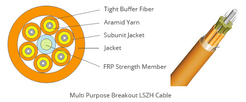
  • LSZH Fiber Optic Cables Tutorial

    Since the 1970s, the wire and cable industry has been using low-smoke, low-halogen materials in a number of applications. The objective was to create a wire and cable jacketing that was not only flame retardant but also did not generate dense, obscuring smoke and toxic or corrosive gases. Several notable fires over the years (such as the King's Cross Fire that killed 32 people in London's underground subway in 1987) increased the awareness of the role that wire and cable jacketing plays in a fire and contributed to a greater adoption of Low-Smoke Zero-Halogen (LSZH) cables.

    With an increase in the amount of cable found in residential, commercial and industrial applications in recent years, there is a greater fuel load in the event of a fire. Wire and cable manufacturers responded by developing materials that had a high resistance to fire while maintaining performance. Low-smoke, zero-halogen compounds proved to be a key materials group that delivered enhanced fire protection performance. Today, LSZH cables are being used in applications beyond the traditional transit, shipboard, military and other confined-space applications. This tutorial is provided to help you learn more about the LSZH fiber optic cables.

    What is LSZH Fiber Optic Cable?

    LSZH Fiber Optic Cable is a kind of fiber optic cable of which the jacket and insulation material are made of special LSZH materials. When these cables come in contact with a flame very little smoke is produced making this product ideal for applications where many people are confined in a certain place (office buildings, train stations, airports, etc.). While a fire may be very harmful in a building, the smoke can cause more damage to people trying to locate exits and inhalation of smoke or gases.


    Fiber optic cable insulation and jacket made from LSZH materials are free of halogenated materials like Fluorine (F), Chlorine (Cl), Bromine (Br), Iodine (I) and Astatine (At), which are reported to be capable of being transformed into toxic and corrosive matter during combustion or decompositions in landfills.

    The most prominent characteristic of LSZH fiber optic cable is safety. LSZH fiber optic cables are used in public spaces like train and subway stations, airports, hospitals, boats and commercial buildings, where toxic fumes would present a danger in the event of a fire. Similarly, low-smoke property is also helpful. More people in fires die from smoke inhalation than any other cause. Using LSZH fiber optic cables which release low smoke and zero halogenated materials in these places would be really important to the safty of people.

    Applications of LSZH Fiber Optic Cables

    There is no doubt that the amount of fiber optic cables installed in buildings has been increasing as data communication proliferated. Central office telecommunication facilities were some of the first places that LSZH cables became common due to the large relative fuel load represented by wire and cable.

    Public Spaces like train stations, hospitals, school, high buidings and commercial centers where the pretection of people and equipment from toxic and corrosive gases is critical should apply LSZH fiber optic cable for the safty of people.

    Data Centers contain large amounts of cables, and are usually enclosed spaces with cooling systems that can potentially disperse combustion byproducts through a large area. In industrial facilities, the relative fuel load of cables will not be at the same level. Other materials burning may also contribute greater amounts of dangerous gases that outweigh the effect of the cables. There have been notable fires where cables burning contributed to corrosion (the Hinsdale Central Office fire is a famous example), but in some instances, better fire response techniques could have prevented this damage.

    Nuclear Industry is another area where LSZH cables have been and will be used in the future. Major cable manufacturers have been producing LSZH cables for nuclear facilities since the early 1990s. The expected construction of new nuclear plants in the U.S. in coming years will almost certainly involve some LSZH cable.

    One of the most important things to understand about LSZH fiber optic cable is that no two products are the same and that there are many factors that will define the suitability of the final product to its application. In fact, research done by a major pulling lubricant supplier tested 27 LSZH compounds and found a huge variation in physical properties. So even using material that meets the base requirements of one of the many specifications available may not result in the best material for the application. Understanding the goals, results and limits of these tests are key to finding the right product. In any case, the trend to consider environmental concerns with a greater weight relative to performance has increased and it can be generally stated that there is an enlarging market for fiber optic cables that can be demonstrated to be environmentally friendly.

    Conclusion

    When selecting or designing a fiber optic cable for any application, the operating enviroments where the fiber optic cable will be used, whether extreme or not, must be considered along with availability, performance, and price, among other things. And when the safety of humans and the enviroment is a consideration, along with high-performance and capability, then LSZH fiber optic cables are what you must specify.

    Warm Tips: When choosing LSZH fiber optic cables, factors such as the environment and price should be considered. An environmental factor such as the temperature of the installation could reduce the flexibility of the cable. Will the application be in an open area or confined? Will other flammable material be present? LSZH fiber optic cables also tend to be higher in cost. 

    Read more »
  • Standards and Recommendations for Fiber Optic Systems

    Many international and national standards govern optical cable characteristics and measurement methods. Some are listed below, but the list is not exhaustive. Releases are subject to change.

    International Standards

    Two main groups are working on international standards: International Electrotechnical Commission (IEC) and International Telecommunication Union (ITU).

    IEC: The IEC is a global organization that prepares and publishes international standards for all electrical, electronic, and related technologies, which serve as a basis for national standardization.

    The IEC is composed of technical committees who prepare technical documents on specific subjects within the scope of an application in order to define the related standards. For example, the technical committee TC86 is dedicated to fiber optics, and its subcommittees SC86A, SC86B, and SC86C focus on specific subjects such as: SC86A: Fibers and CablesSC86B: Fiber Optic Interconnecting Devices and Passive ComponentsSC86C: Fiber Optic Systems and Active Devices
    ITU: The ITU is an international organization that defines guidelines, technical characteristics, and specifications of telecommunications systems, networks, and services. It includes optical fiber performance and test and measurement applications and consists of three different sectors: Radiocommunication Sector (ITU-R)Telecommunication Standardization Sector (ITU-T)Telecommunication Development Sector (ITU-D)


    National Standards

    In addition to the international standards, countries or union of countries define their own standards in order to customize or fine tune the requirements to the specificity of their country.

    European Telecommunications Standards Institute

    The European Telecommunications Standards Institute (ETSI) defines telecommunications standards and is responsible for the standardization of Information and Communication Technologies (ICT) within Europe. These technologies include telecommunications, broadcasting, and their related technologies, such as intelligent transportation and medical electronics.

    Telecommunication Industries Association / Electronic Industries Alliance

    The Telecommunication Industries Association (TIA) provides additional recommendations for the United States. TIA is accredited by the American National Standards Institute (ANSI) to develop industry standards for a wide variety of telecommunications products. The committees and subcommittees define standards for fiber optics, user premises equipment, network equipment, wireless communications, and satellite communications.

    NOTE: There are many other standard organizations that exist in other countries.


    Fiber Optic Standards

    By IEC: IEC 61300-3-35: Fibre Optic Connector End Face Visual InspectionIEC 60793-1 and -2: Optical Fibers (includes several parts)IEC 60794-1, -2, and -3: Optical Fiber Cables
    By ITU: G.651: Characteristics of 50/125 μm Multimode Graded-index Optical FiberG.652: Characteristics of Single-mode Optical Fiber and CableG.653: Characteristics of Single-mode Dispersion Shifted Optical Fiber and CableG.654: Characteristics of Cut-off Shifted Single-mode Optical Fiber and CableG.655: Characteristics of Non-zero Dispersion Shifted Single-mode Optical Fiber and CableG.656: Characteristics of Non-zero Dispersion Shifted Fiber for Wideband TransportG.657: Characteristics of a Bending Loss Insensitive Single-mode Fiber for Access Networks


    Test and Measurement Standards

    Generic Test Standards: IEC 61350: Power Meter CalibrationIEC 61746: OTDR CalibrationG.650.1: Definition and Test Methods for Linear, Deterministic Attributes of Single-mode Fiber and CableG.650.2: Definition and Test Methods for Statistical and Non-linear Attributes of Single-mode Fiber and Cable
    PMD Test Standards: G.650.2: Definition and Test Methods for Statistical and Non- linear Attributes of Single-mode Fiber and CableIEC 60793 1-48: Optical Fibers—Part 1-48: Measurement Methods and Test Procedures—Polarization Mode DispersionIEC/TS 61941: Technical Specifications for Polarization Mode Dispersion Measurement Techniques for Single-mode Optical FiberIEC 61280-3/TIA/TR-1029: Calculation of PolarizationTIA 455 FOTP-124A: Polarization Mode Dispersion Measurement for Single-mode Optical Fiber and Cable Assemblies by InterferometryTIA 455 FOTP-113: Polarization Mode Dispersion Measurement of Single-mode Optical Fiber by the Fixed Analyzer MethodTIA 455 FOTP-122A: Polarization Mode Dispersion Measurement for Single-mode Optical Fiber by the Stokes Parameter MethodTIA TSB-107: Guidelines for the Statistical Specification of Polarization Mode Dispersion on Optical Fiber CablesTIA 455-196: Guidelines for Polarization Mode Measurements in Single-mode Fiber Optic Components and DevicesGR-2947-CORE: Generic Requirements for Portable Polarization Mode Dispersion (PMD) Test SetsIEC 61280-4-4: Polarization Mode Dispersion Measurement for Installed LinksTIA 445 FOTP-243: Polarization Mode Dispersion Measurement for Installed Single-mode Optical Fibers by Wavelength-scanning OTDR and State of Polarization Analysis
    CD Test Standards: G.650.1: Definition and Test Methods for Linear, Deterministic Attributes of Single-mode Fiber and CableIEC 60793 1-42: Optical Fibers—Part 1-42: Measurement Methods and Test Procedures—Chromatic DispersionIEC 61744: Calibration of Fiber Optic Chromatic Dispersion Test SetsTIA/EIA FOTP-175-B: Chromatic Dispersion Measurement of Single-mode Optical FibersGR-761-CORE: Generic Criteria for Chromatic Dispersion Test SetsGR-2854-CORE: Generic Requirements for Fiber Optic Dispersion Compensators
    Read more »
RSS