This white paper provides an overview of the Cisco StackWise and Cisco StackWise Plus technologies and the specific mechanisms that they use to create a unified, logical switching architecture through the linkage of multiple, fixed configuration switches. This paper focuses on the following critical aspects of the Cisco StackWise and Cisco StackWise Plus technologies: stack interconnect behavior, stack creation and modification; Layer 2 and Layer 3 forwarding; and quality-of-service (QoS) mechanisms. The goal of the paper is to help the reader understand how the Cisco StackWise and StackWise Plus technologies deliver advanced performance for voice, video, and Gigabit Ethernet applications. First, this white paper will discuss the Cisco Catalyst 3750 Series Switches and StackWise and second, the Cisco Catalyst 3750-E and Catalyst 3750-X Series Switches with StackWise Plus will be discussed, highlighting the differences between the two. Please note that the Cisco Catalyst 3750-E and Catalyst 3750-X will run StackWise Plus when connected to a stack of all Cisco Catalyst 3750-E and Catalyst 3750-X switches, while it will run StackWise if there is one or more Cisco Catalyst 3750 in the stack. (See Figures 1 and 2.)
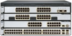
Figure 1. Stack of Cisco Catalyst 3750 Series Switches with StackWise Technology
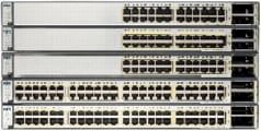
Figure 2. Stack of Cisco Catalyst 3750-E Series Switches with StackWise and StackWise Plus Technologies
Technology Overview
Cisco StackWise technology provides an innovative new method for collectively utilizing the capabilities of a stack of switches. Individual switches intelligently join to create a single switching unit with a 32-Gbps switching stack interconnect. Configuration and routing information is shared by every switch in the stack, creating a single switching unit. Switches can be added to and deleted from a working stack without affecting performance.
The switches are united into a single logical unit using special stack interconnect cables that create a bidirectional closed-loop path. This bidirectional path acts as a switch fabric for all the connected switches. Network topology and routing information is updated continuously through the stack interconnect. All stack members have full access to the stack interconnect bandwidth. The stack is managed as a single unit by a master switch, which is elected from one of the stack member switches.
Each switch in the stack has the capability to behave as a master or subordinate (member) in the hierarchy. The master switch is elected and serves as the control center for the stack. Both the master member switches act as forwarding processors. Each switch is assigned a number. Up to nine separate switches can be joined together. The stack can have switches added and removed without affecting stack performance.
Each stack of Cisco Catalyst 3750 Series Switches has a single IP address and is managed as a single object. This single IP management applies to activities such as fault detection, virtual LAN (VLAN) creation and modification, security, and QoS controls. Each stack has only one configuration file, which is distributed to each member in the stack. This allows each switch in the stack to share the same network topology, MAC address, and routing information. In addition, it allows for any member to become the master, if the master ever fails.
The Stack Interconnect Functionality
Cisco StackWise technology unites up to nine individual Cisco Catalyst 3750 switches into a single logical unit, using special stack interconnect cables and stacking software. The stack behaves as a single switching unit that is managed by a master switch elected from one of the member switches. The master switch automatically creates and updates all the switching and optional routing tables. A working stack can accept new members or delete old ones without service interruption.
Bidirectional Flow
To efficiently load balance the traffic, packets are allocated between two logical counter-rotating paths. Each counter-rotating path supports 16 Gbps in both directions, yielding a traffic total of 32 Gbps bidirectionally. The egress queues calculate path usage to help ensure that the traffic load is equally partitioned.
Whenever a frame is ready for transmission onto the path, a calculation is made to see which path has the most available bandwidth. The entire frame is then copied onto this half of the path. Traffic is serviced depending upon its class of service (CoS) or differentiated services code point (DSCP) designation. Low-latency traffic is given priority.
When a break is detected in a cable, the traffic is immediately wrapped back across the single remaining 16-Gbps path to continue forwarding.
Online Stack Adds and Removals
Switches can be added and deleted to a working stack without affecting stack performance. When a new switch is added, the master switch automatically configures the unit with the currently running Cisco IOS ® Software image and configuration of the stack. The stack will gather information such as switching table information and update the MAC tables as new addresses are learned. The network manager does not have to do anything to bring up the switch before it is ready to operate. Similarly, switches can be removed from a working stack without any operational effect on the remaining switches. When the stack discovers that a series of ports is no longer present, it will update this information without affecting forwarding or routing.
Physical Sequential Linkage
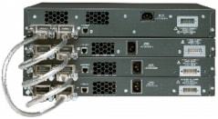
The switches are physically connected sequentially, as shown in Figure 3. A break in any one of the cables will result in the stack bandwidth being reduced to half of its full capacity. Subsecond timing mechanisms detect traffic problems and immediately institute failover. This mechanism restores dual path flow when the timing mechanisms detect renewed activity on the cable.
Figure 3. Cisco StackWise Technology Resilient Cabling
Subsecond Failover
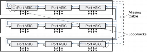
Within microseconds of a breakage of one part of the path, all data is switched to the active half of the bidirectional path (Figure 4).
Figure 4. Loopback After Cable Break
The switches continually monitor the stack ports for activity and correct data transmission. If error conditions cross a certain threshold, or there is insufficient electromagnetic contact of the cable with its port, the switch detecting this then sends a message to its nearest neighbor opposite from the breakage. Both switches then divert all their traffic onto the working path.
Single Management IP Address
The stack receives a single IP address as a part of the initial configuration. After the stack IP address is created, the physical switches linked to it become part of the master switch group. When connected to a group, each switch will use the stack IP address. When a new master is elected, it uses this IP address to continue interacting with the network.
Stack Creation and Modification
Stacks are created when individual switches are joined together with stacking cables. When the stack ports detect electromechanical activity, each port starts to transmit information about its switch. When the complete set of switches is known, the stack elects one of the members to be the master switch, which will be responsible for maintaining and updating configuration files, routing information, and other stack information. The entire stack will have a single IP address that will be used by all the switches.
1:N Master Redundancy
1:N master redundancy allows each stack member to serve as a master, providing the highest reliability for forwarding. Each switch in the stack can serve as a master, creating a 1:N availability scheme for network control. In the unlikely event of a single unit failure, all other units continue to forward traffic and maintain operation.
Master Switch Election
The stack behaves as a single switching unit that is managed by a master switch elected from one of the member switches. The master switch automatically creates and updates all the switching and optional routing tables. Any member of the stack can become the master switch. Upon installation, or reboot of the entire stack, an election process occurs among the switches in the stack. There is a hierarchy of selection criteria for the election.
1. User priority - The network manager can select a switch to be master.
2. Hardware and software priority - This will default to the unit with the most extensive feature set. The Cisco Catalyst 3750 IP Services (IPS) image has the highest priority, followed by Cisco Catalyst 3750 switches with IP Base Software Image (IPB).
Catalyst 3750-E and Catalyst 3750-X run the Universal Image. The feature set on the universal image is determined by the purchased license. The "show version" command will list operating license level for each switch member in the stack.
3. Default configuration - If a switch has preexisting configuration information, it will take precedence over switches that have not been configured.
4. Uptime - The switch that has been running the longest is selected.
5. MAC address - Each switch reports its MAC address to all its neighbors for comparison. The switch with the lowest MAC address is selected.
Master Switch Activities
The master switch acts as the primary point of contact for IP functions such as Telnet sessions, pings, command-line interface (CLI), and routing information exchange. The master is responsible for downloading forwarding tables to each of the subordinate switches. Multicast and unicast routing tasks are implemented from the master. QoS and access control list (ACL) configuration information is distributed from the master to the subordinates. When a new subordinate switch is added, or an existing switch removed, the master will issue a notification of this event and all the subordinate switches will update their tables accordingly.
Shared Network Topology Information
The master switch is responsible for collecting and maintaining correct routing and configuration information. It keeps this information current by periodically sending copies or updates to all the subordinate switches in the stack. When a new master is elected, it reapplies the running configuration from the previous master to help ensure user and network continuity. Note that the master performs routing control and processing. Each individual switch in the stack will perform forwarding based on the information distributed by the master.
Subordinate Switch Activities
Each switch has tables for storing its own local MAC addresses as well as tables for the other MAC addresses in the stack. The master switch keeps tables of all the MAC addresses reported to the stack. The master also creates a map of all the MAC addresses in the entire stack and distributes it to all the subordinates. Each switch becomes aware of every port in the stack. This eliminates repetitive learning processes and creates a much faster and more efficient switching infrastructure for the system.
Subordinate switches keep their own spanning trees for each VLAN that they support. The StackWise ring ports will never be put into a Spanning Tree Protocol blocking state. The master switch keeps a copy of all spanning tree tables for each VLAN in the stack. When a new VLAN is added or removed, all the existing switches will receive a notification of this event and update their tables accordingly.
Subordinate switches wait to receive copies of the running configurations from the master and begin to start transmitting data upon receipt of the most current information. This helps ensure that all the switches will use only the most current information and that there is only one network topology used for forwarding decisions.
Multiple Mechanisms for High Availability
The Cisco StackWise technology supports a variety of mechanisms for creating high resiliency in a stack.
• CrossStack EtherChannel® technology - Multiple switches in a stack can create an EtherChannel connection. Loss of an individual switch will not affect connectivity for the other switches.
• Equal cost routes - Switches can support dual homing to different routers for redundancy.
• 1:N master redundancy - Every switch in the stack can act as the master. If the current master fails, another master is elected from the stack.
• Stacking cable resiliency - When a break in the bidirectional loop occurs, the switches automatically begin sending information over the half of the loop that is still intact. If the entire 32 Gbps of bandwidth is being used, QoS mechanisms will control traffic flow to keep jitter and latency-sensitive traffic flowing while throttling lower priority traffic.
• Online insertion and removal - Switches can be added and deleted without affecting performance of the stack.
• Distributed Layer 2 forwarding - In the event of a master switch failure, individual switches will continue to forward information based on the tables they last received from the master.
• RPR+ for Layer 3 resiliency - Each switch is initialized for routing capability and is ready to be elected as master if the current master fails. Subordinate switches are not reset so that Layer 2 forwarding can continue uninterrupted. Layer 3 Nonstop Forwarding (NSF) is also supported when two or more nodes are present in a stack.
Layer 2 and Layer 3 Forwarding
Cisco StackWise technology offers an innovative method for the management of Layer 2 and Layer 3 forwarding. Layer 2 forwarding is done with a distributed method. Layer 3 is done in a centralized manner. This delivers the greatest possible resiliency and efficiency for routing and switching activities across the stack.
Forwarding Resiliency During Master Change
When one master switch becomes inactive and while a new master is elected, the stack continues to function. Layer 2 connectivity continues unaffected. The new master uses its hot standby unicast table to continue processing unicast traffic. Multicast tables and routing tables are flushed and reloaded to avoid loops. Layer 3 resiliency is protected with NSF, which gracefully and rapidly transitions Layer 3 forwarding from the old to new master node.
High-Availability Architecture for Routing Resiliency Using Routing Processor Redundancy+
The mechanism used for high availability in routing during the change in masters is called Routing Processor Redundancy+ (RPR+). It is used in the Cisco 12000 and 7500 Series Routers and the Cisco Catalyst 6500 Series Switch products for high availability. Each subordinate switch with routing capability is initialized and ready to take over routing functions if the master fails. Each subordinate switch is fully initialized and connected to the master. The subordinates have identical interface addresses, encapsulation types, and interface protocols and services. The subordinate switches continually receive and integrate synchronized configuration information sent by the current master and monitor their readiness to operate through the continuous execution of self-tests. Reestablishment of routes and links happens more quickly than in normal Layer 3 devices because of the lack of time needed to initialize the routing interfaces. RPR+ coupled with NSF provides the highest performance failover forwarding.
Adding New Members
When the switching stack has established a master, any new switch added afterward automatically becomes a subordinate. All the current routing and addressing information is downloaded into the subordinate so that it can immediately begin transmitting traffic. Its ports become identified with the IP address of the master switch. Global information, such as QoS configuration settings, is downloaded into the new subordinate member.
Cisco IOS Software Images Must Be Identical
The Cisco StackWise technology requires that all units in the stack run the same release of Cisco IOS Software. When the stack is first built, it is recommended that all of the stack members have the same software feature set - either all IP Base or all IP Services. This is because later upgrades of Cisco IOS Software mandate that all the switches to be upgraded to the same version as the master.
Automatic Cisco IOS Software Upgrade/Downgrade from the Master Switch
When a new switch is added to an existing stack, the master switch communicates with the switch to determine if the Cisco IOS Software image is the same as the one on the stack. If it is the same, the master switch sends the stack configuration to the device and the ports are brought online. If the Cisco IOS Software image is not the same, one of three things will occur:
1. If the hardware of the new switch is supported by the Cisco IOS Software image running on the stack, the master will by default download the Cisco IOS Software image in the master's Flash memory to the new switch, send down the stack configuration, and bring the switch online.
2. If the hardware of the new switch is supported by the Cisco IOS Software image running on the stack and the user has configured a Trivial File Transfer Protocol (TFTP) server for Cisco IOS Software image downloads, then the master will automatically download the Cisco IOS Software image from the TFTP server to the new switch, configure it, then bring it online.
3. If the hardware of the new switch is not supported by the Cisco IOS Software image running on the stack, the master will put the new switch into a suspended state, notify the user of a version incompatibility, and wait until the user upgrades the master to a Cisco IOS Software image that supports both types of hardware. The master will then upgrade the rest of the stack to this version, including the new switch, and bring the stack online.
Upgrades Apply to All Devices in the Stack
Because the switch stack behaves like a single unit, upgrades apply universally to all members of the stack at once. This means that if an original stack contains a combination of IP Base and IP services software feature sets on the various switches, the first time a Cisco IOS Software upgrade is applied, all units in the stack will take on the characteristic of the image applied. While this makes it much more efficient to add functionality to the stack, it is important to make sure all applicable upgrade licenses have been purchased before allowing units to be upgraded from IP Base .to IP Services functions. Otherwise, those units will be in violation of Cisco IOS Software policy.
Smart Unicast and Multicast - One Packet, Many Destinations
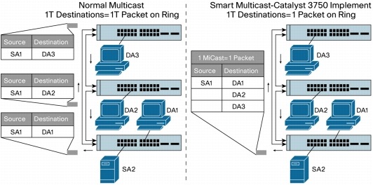
The Cisco StackWise technology uses an extremely efficient mechanism for transmitting unicast and multicast traffic. Each data packet is put on the stack interconnect only once. This includes multicast packets. Each data packet has a 24-byte header with an activityJame list for the packet as well as a QoS designator. The activity list specifies the port destination or destinations and what should be done with the packet. In the case of multicast, the master switch identifies which of the ports should receive a copy of the packets and adds a destination index for each port. One copy of the packet is put on the stack interconnect. Each switch port that owns one of the destination index addresses then copies this packet. This creates a much more efficient mechanism for the stack to receive and manage multicast information (Figure 5).
Figure 5. Comparison of Normal Multicast in Stackable Switches and Smart Multicast in Cisco Catalyst 3750 Series Switches Using Cisco StackWise Technology
QoS Mechanisms
QoS provides granular control where the user meets the network. This is particularly important for networks migrating to converged applications where differential treatment of information is essential. QoS is also necessary for the migration to Gigabit Ethernet speeds, where congestion must be avoided.
QoS Applied at the Edge
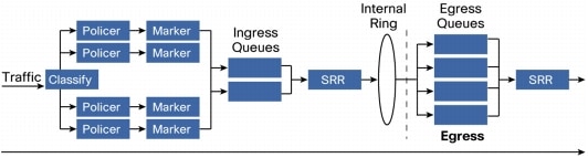
Cisco StackWise supports a complete and robust QoS model, as shown in Figure 6.
Figure 6. QoS Model
The Cisco Catalyst 3750-E, Catalyst 3750-X and Cisco Catalyst 3750 support 2 ingress queues and 4 egress queues. Thus the Cisco Catalyst 3750-E, Catalyst 3750-X and Cisco Catalyst 3750 switches. support the ability to not only limit the traffic destined for the front side ports, but they can also limit the amounts of and types of traffic destined for the stack ring interconnect. Both the ingress and egress queues can be configured for one queue to be serviced as a priority queue that gets completely drained before the other weighted queue(s) get serviced. Or, each queue set can be configured to have all weighted queues.
StackWise employs Shaped Round Robin (SRR). SRR is a scheduling service for specifying the rate at which packets are dequeued. With SRR there are two modes, Shaped and Shared (default). Shaped mode is only available on the egress queues. Shaped egress queues reserve a set of port bandwidth and then send evenly spaced packets as per the reservation. Shared egress queues are also guaranteed a configured share of bandwidth, but do not reserve the bandwidth. That is, in Shared mode, if a higher priority queue is empty, instead of the servicer waiting for that reserved bandwidth to expire, the lower priority queue can take the unused bandwidth. Neither Shaped SRR nor Shared SRR is better than the other. Shared SRR is used when one wants to get the maximum efficiency out of a queuing system, because unused queue slots can be used by queues with excess traffic. This is not possible in a standard Weighted Round Robin (WRR). Shaped SRR is used when one wants to shape a queue or set a hard limit on how much bandwidth a queue can use. When one uses Shaped SRR one can shape queues within a ports overall shaped rate. In addition to queue shaping, the Cisco Catalyst 3750-E can rate limit a physical port. Thus one can shape queues within an overall rate-limited port value.
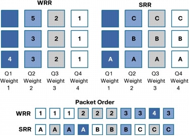
As stated earlier, SRR differs from WRR. In the examples shown in figure 7, strict priority queuing is not configured and Q4 is given the highest weight, Q3 lower, Q2 lower, and Q1 the lowest. With WRR, queues are serviced based on the weight. Q1 is serviced for Weight 1 period of time, Q2 is served for Weight 2 period of time, and so forth. The servicing mechanism works by moving from queue to queue and services them for the weighted amount of time. With SRR weights are still followed; however, SRR services the Q1, moves to Q2, then Q3 and Q4 in a different way. It doesn't wait at and service each queue for a weighted amount of time before moving on to the next queue. Instead, SRR makes several rapid passes at the queues, in each pass, each queue may or may not be serviced. For each given pass, the more highly weighted queues are more likely to be serviced than the lower priority queues. Over a given time, the number of packets serviced from each queue is the same for SRR and WRR. However, the ordering is different. With SRR, traffic has a more evenly distributed ordering. With WRR one sees a bunch of packets from Q1 and then a bunch of packets from Q2, etc. With SRR one sees a weighted interleaving of packets. In the example in Figure 7, for WRR, all packets marked 1 are serviced, then 2, then 3, and so on till 5. In SRR, all A packets are serviced, then B, C, and D. SRR is an evolution of WRR that protects against overwhelming buffers with huge bursts of traffic by using a smoother round-robin mechanism.
Figure 7. Queuing
In addition to advanced queue servicing mechanisms, congestion avoidance mechanisms are supported. Weighted tail drop (WTD) can be applied on any or all of the ingress and egress queues. WTD is a congestion-avoidance mechanism for managing the queue lengths and providing drop precedences for different traffic classifications. Configurable thresholds determine when to drop certain types of packets. The thresholds can be based on CoS or DSCP values. As a queue fills up, lower priority packets are dropped first. For example, one can configure WTD to drop CoS 0 through 5 when the queue is 60% full. In addition, multiple thresholds and levels can be set on a per queue basis.
Jumbo Frame Support
The Cisco StackWise technology supports granular jumbo frames up to 9 KB on the 10/100/1000 copper ports for Layer 2 forwarding. Layer 3 forwarding of jumbo packets is not supported by the Cisco Catalyst 3750. However, the Cisco Catalyst 3750-E and Catalyst 3750-X. do support Layer 3 jumbo frame forwarding.
Smart VLANs
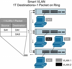
VLAN operation is the same as multicast operation. If the master detects information that is destined for multiple VLANs, it creates one copy of the packet with many destination addresses. This enables the most effective use of the stack interconnect (Figure 8).
Figure 8. Smart VLAN Operations
Cross-Stack EtherChannel Connections
Because all the ports in a stack behave as one logical unit, EtherChannel technology can operate across multiple physical devices in the stack. Cisco IOS Software can aggregate up to eight separate physical ports from any switches in the stack into one logical channel uplink. Up to 48 EtherChannel groups are supported on a stack.
StackWise Plus
StackWise Plus is an evolution of StackWise. StackWise Plus is only supported on the Cisco Catalyst 3750-E and Catalyst 3750-X switch families. The two main differences between StackWise Plus and StackWise are as follows:
1. For unicast packets, StackWise Plus supports destination striping, unlike StackWise support of source stripping. Figure 9 shows a packet is being sent from Switch 1 to Switch 2. StackWise uses source stripping and StackWise Plus uses destination stripping. Source stripping means that when a packet is sent on the ring, it is passed to the destination, which copies the packet, and then lets it pass all the way around the ring. Once the packet has traveled all the way around the ring and returns to the source, it is stripped off of the ring. This means bandwidth is used up all the way around the ring, even if the packet is destined for a directly attached neighbor. Destination stripping means that when the packet reaches its destination, it is removed from the ring and continues no further. This leaves the rest of the ring bandwidth free to be used. Thus, the throughput performance of the stack is multiplied to a minimum value of 64 Gbps bidirectionally. This ability to free up bandwidth is sometimes referred to as spatial reuse. Note: even in StackWise Plus broadcast and multicast packets must use source stripping, because the packet may have multiple targets on the stack.
Figure 9. Stripping
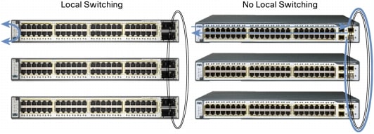
2. StackWise Plus can locally switch. StackWise cannot. Furthermore, in StackWise, since there is no local switching and since there is source stripping, even locally destined packets must traverse the entire stack ring. (See Figure 10.)
Figure 10. Switching
3. StackWise Plus will support up to 2 line rate 10 Gigabit Ethernet ports per Cisco Catalyst 3750-E.
Combining StackWise Plus and StackWise in a Single Stack
Cisco Catalyst 3750-E and Catalyst 3750-X StackWise Plus and Cisco Catalyst 3750 StackWise switches can be combined in the same stack. When this happens, the Cisco Catalyst 3750-E, or Catalyst 3750-Xswitches negotiate from StackWise Plus mode down to StackWise mode. That is, they no longer perform destination stripping. However, the Cisco Catalyst 3750-E and the Catalyst 3750-X will retain its ability to perform local switching.
Management
Products using the Cisco StackWise and StackWise Plus technologies can be managed by the CLI or by network management packages. Cisco Cluster Management Suite (CMS) Software has been developed specifically for management of Cisco stackable switches. Special wizards for stack units in Cisco CMS Software allow the network manager to configure all the ports in a stack with the same profile. Predefined wizards for data, voice, video, multicast, security, and inter-VLAN routing functions allow the network manager to set all the port configurations at once.
The Cisco StackWise and StackWise Plus technologies are also manageable by CiscoWorks.
Summary
Cisco StackWise and StackWise Plus technologies allow you to increase the resiliency and the versatility of your network edge to accommodate evolution for speed and converged applications.
Read more »